Welcome to Kabelassistent


Kabelassistent is a product range that includes the complete equipment for wire harness assembly.
Kabelassistent includes a comprehensive modular system for faster wire harness assembly.
Fast measurement technology helps your employees to produce error-free wire harnesses from the very first wire harness.
And Kabelassistent is a light-guided work process that enables your new employees to achieve high productivity in a short time with a steep learning curve.
For you, Kabelassistent means transparency and control for your work preparation and assembly planning.
In short, Cable Assistant is the digitalization and modularization of the wire harness assembly board.
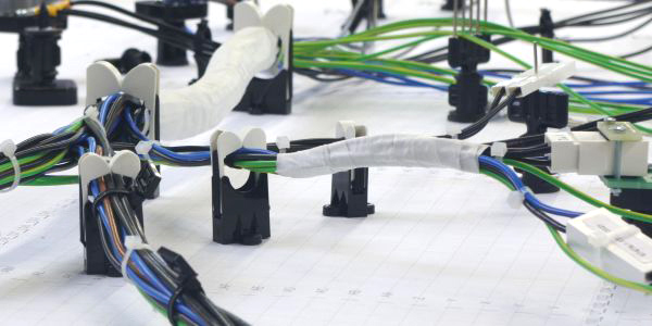
You can offer your customers pre-series and small batches faster and at a lower entry price.
You can move assembly locations around the globe with the click of a mouse.
You can react quickly and flexibly to changes in demand.
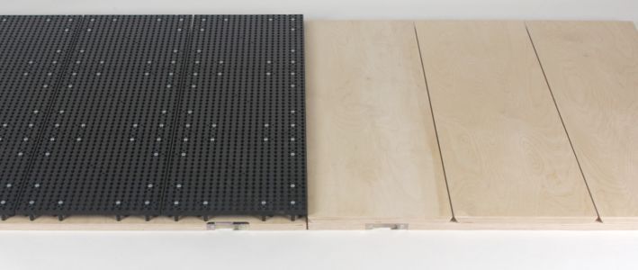
On the Devboard assembly boards, you simply plug the assembly board together using the Quick-Build grid system from Panduit and our Kitconnect adapter kit.
You screw Panduit guides and mating connectors from our Kitconnect adapter kit onto the Prodboard assembly boards so you can manufacture for years to come.
Thanks to the interchangeability of Devboard and Prodboard, you can easily add more assembly boards when demand peaks.
Good employees with smart ideas are rare and valuable. By building the adapters for the mating connectors of the measurement technology with the Kitconnect construction kit, the 3D frame for high connector densities and the guide elements from Panduit, you can use ready-made parts and save your employees' creative time.
In minutes, you can unscrew an assembly board and disassemble the Kitconnect adapters into their standard parts. And should an unexpected spare parts order come in? Then put together an assembly board for a job on a Devboard again in no time at all.
Thanks to the quick setup of mating connectors with the Kitconnect adapter kit, the simple wiring on the surface of the Devboard and Prodboard and the wizard for linking the measurement channels, measuring the wire harnesses in production is worthwhile even for small quantities.
Thanks to the fast measurement technology, Kabelassistent recognizes every connection in a fraction of a second and confirms it as correct or incorrect. In the event of incorrect connections, Kabelassistent shows in plain text what the correct connection should look like.
Instead of reading routing lists or asking supervisors for help, Kabelassistent shows them what belongs where with Harness-By-Light, i.e. with Pick-By-Light and laser projection. Adapted to the qualifications of each individual employee.
Kabelassistent is network-based throughout. All communication for controlling the measurement technology, pick-by-light and laser projector runs via normal network cables or WLAN. There are no PCs in manufacturing, no permanently connected monitors, no switch cabinets and no cabling.
All you need is protected access to the production site network. You can then log in to the local server with your browser like on-site employees and follow every step as if you were standing there.
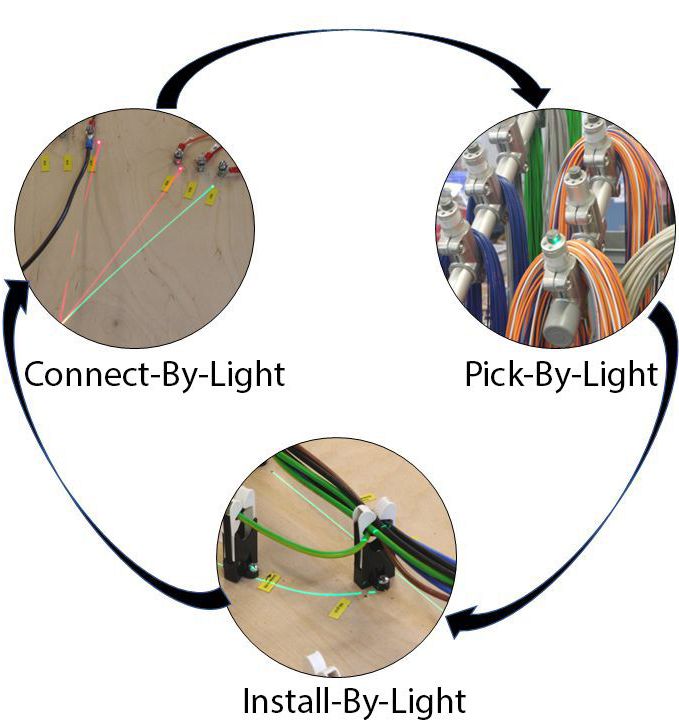
Pick-By-Light + Install-By-Light + Connect-By-Light = Harness-By-Light
Pick-By-Light – Confirmation with the button triggers Install-By-Light, the display of the laying path.
Install-By-Light – Lay one or more strands according to the laser line.
Connect-By-Light – The continuity tester on the thumbnail. Correct pinning triggers Pick-By-Light of the next strands.
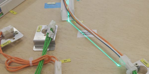
Your employees no longer use laying lists.
You have to give fewer instructions.
The learning curve for new employees is steeper.
Even employees with fewer qualifications can lay wire harnesses productively.
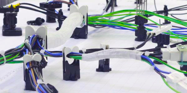
Both the Devboard assembly boards equipped with Quick-Build and the Prodboard wooden boards have slots at 30 cm intervals into which you insert the modular cables from above.
You only need one type of cable for all the cabling on a board. And it is so inexpensive that the cables can remain on the board when the board is changed.
The RJ45 modular connector offers the optimum in terms of connection time, price, contact resistance and number of possible mating cycles. It has been proven a billion times over in telecommunications and networking.
With the mini marshalling distributor pin splitter, you route the required measurement channels to the contacts of the mating connector. The remaining measuring channels you can bridge to another pin splitter and use them for another adapter. An intuitive color system for the patch cables helps you do this.
Each measurement channel is an input and output at the same time. There are no situations where inputs are connected on both sides of a strand or outputs on both sides.
At the Kabelporter table, you plug the measurement cabling into transfer modules. Place excess lengths in loops in the brackets provided. Finally, close the covers of the cable porter. All cabling is now protected.
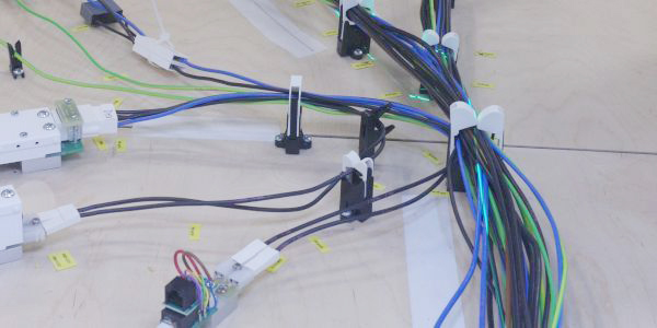
No drilling, no drilling dust.
Works equally well on wooden board and quick build.
Easy to make changes without leaving holes.
No work on the underside of the assembly board.
No soldering or crimping of wires.
No need to lay individual wires for each channel.
Unlimited recyclability of wooden boards.
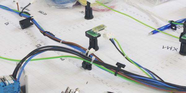
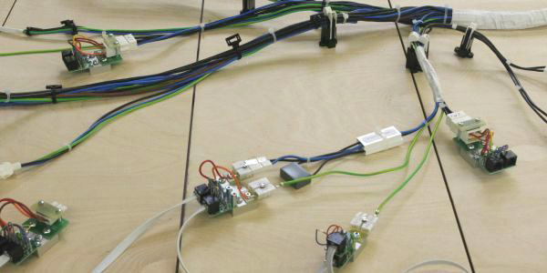
Devboard is our answer to the need to set up an assembly board and equip it with measurement technology in the shortest possible time. You can start producing pre-series, small series and spare parts in no time at all.
Prodboard is the exact opposite. Thanks to the fixed screwing of the guide elements and mating plugs, it provides the basis for years of production, even with rustic cross-sections or hard-working employees.s
The decision is not whether one fits or the other, but when which of the two fits better. This is because both boards have the same grooves for wiring the measuring technology and can also be locked in the Kabelporter table in the same way.
From this, we have developed a strategy for maximum flexibility.
For the pilot series of a new wiring harness or for small series, use the Devboard. Place a grid paper on the laying board. Simply insert the Quick-Build mounting feet through and for the measurement cables, cut the paper over the cable slots with the cutter.
If the setup fits, then draw all the guide elements and mating plugs on the grid paper. Also note the connections to the measurement technology.
At the end of the first series, remove all guide elements and mating plugs. Pull the measurement cables out of the slots and tape the incisions in the screen paper. You scan the grid paper and save it.
If necessary, you can use the scan of the grid paper as a background to create a plan in the CAD system, edit it with a drawing program or leave it as it is.
For serial production, have the plan printed and laminated. Place it on a Prodboard as a base. Screw the guide elements and the same mating plugs onto it at the marked points. For the measurement cables, cut the plan again and tape the slots closed after inserting the cables. Use the same plan to build as many identical assembly boards as you need for your planned production capacity.
To repeat a small series, temporarily increase production capacity or produce spare parts after the end of series production, place the plan on a Devboard as at the beginning and attach the guide elements and mating plugs again in a few minutes.
Minimal costs for the first series.
Lower set-up costs for small series.
Global relocation of production sites without transporting the assembly boards.
Flexible response to peaks in demand.
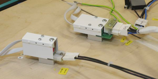
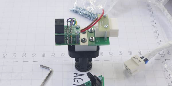
Would you like to minimize the manpower required to set up installation boards? We offer you the option of using standardized, prefabricated parts from our construction kits to set up assembly boards. This allows us to take some of the work off your hands.We have developed the Kitconnect construction kit to assemble the adapters for the measurement technology. It contains ready-made components for the four tasks of an adapter:
Fastening to the assembly board or the Quick-Build mounting platform.
This task is performed by the base rail in Kitconnect. We supply base rails from 20 mm to 200 mm wide. It is the basis for the stable fastening of the mounting plate, which absorbs even heavy assembly forces.
Fastening the mating connector.
We also supply mounting plates from 20 mm to 200 mm wide for this purpose. They are made of 3.2 mm thick GRP and are pre-punched with a 5 mm grid. You can attach both plug housings and bare contacts to them. A suitable universal fastening set and a handy adhesive system are available for quick fastening of plug housings.
Connecting the mating plug to the RJ45 cabling system.
The most important part is the pin splitter, a mini connection module that you can screw onto the base rail side by side or on top of each other as required. We also offer matching pigtails that you connect to the contacts of the mating plug and patch connectors to make free channels on an output pin splitter available to the next adapter.
Cover.
To safely separate the pigtails and patch connectors from the strands of the wiring harness, there are covers that you can vary in width and height to suit the layout of the pin splitter.
Another construction kit is the 3D frame.
You use it to simulate central connection areas of the wiring harness. Many cables often come together at the rear panels of devices or control boards. At these points, the connector density is higher than can be built up on the assembly board.
The 3D frame offers you a quick solution for these difficult cases. In a frame that stands vertically on the assembly board, you can mount high-density Kitconnect adapters on carrier rails. Cover the frame on the wiring harness side with a white cardboard panel, into which you can easily cut the cut-outs for the mating plugs with a cutter.
Email: info@kabelassistent.eu
Tel.: ++49 / 76 35 / 82 716 50
Fax: ++49 / 76 35 / 82 716 20
It is generally possible to use our website without providing personal data.