Welcome to Kabelassistent


Do you produce small series of many different wire harnesses or large series continuously over many years? Or a combination of both? For example, low-priced pilot series and sample series at short notice, followed by years of series production for the same products? Or do you receive occasional orders for small series as spare parts years after the end of series production?
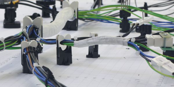
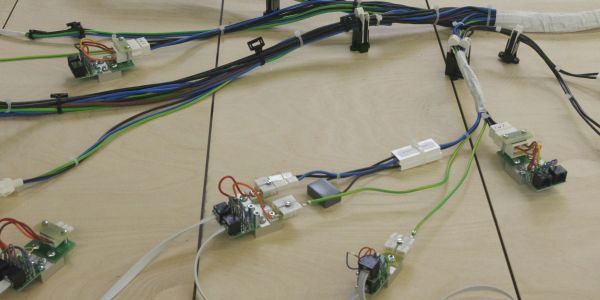
We have developed two assembly boards for these requirements:
- Devboard, from Development Board, for quick assembly but with limited load-bearing capacity and as a counterpart Prodboard, and
- Production Board, for the classic screwed construction, which requires more time, but forms the stable basis for years of production, even when the going gets tough.
Devboard and Prodboard have the same dimensions. Therefore, in the lifecycle of a wire harness, it is often not a question of which of the two is right, but when which one fits best. If you want to offer your customer the pilot series of a new product quickly and cost-effectively, the Devboard is ideal. Later in the series, you can transfer the assembly from the Devboard to one or more Prodboards. If you need to provide higher production capacities temporarily, a Devboard assembly is again suitable. And if your customer orders a subsequent delivery of spare parts years after the end of series production, long after you have reused all the Prodboards for new products, the quickest way is to set up another assembly board on a Devboard. This saves you storage space for unused assembly boards.
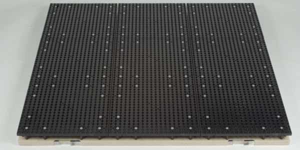
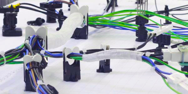
Devboard is the ideal assembly board for the production of pilot series and small series that you produce once or only at longer intervals. It is covered with Panduit Quick-Build boards.
As soon as you have received the cutting list and the sample wiring harness from the customer, start assembling the individual strands and setting up the assembly board at the same time.
To do this, equip the Kabelporter system assembly table with the Devboard grid installation boards. Place a coordinate plot on the Devboards, on which you can easily sketch a laying plan later.
Lay out the sample wiring harness on the coordinate plot. Place the prepared measuring adapters and the guide elements on the Devboard through the coordinate paper. If something does not fit, you can easily reposition elements on the Devboard. Then connect the measuring adapters to the transfer modules of the measuring channels on the table using flat cables and connect free channels to each other using the next measuring adapter.
If the arrangement of all elements fits, write the name of the plugs or terminals and their connections to the transfer modules or to other measuring adapters by hand next to the measuring adapters using a felt-tip pen. Also draw in the guide elements and cable ties. You can scan the sketch of the installation plan created in this way or transfer it to a CAD drawing.
You can import the connection list into the Kabelassistent program at the same time as setting it up on the assembly board.
The last step is to unplug the sample wiring harness from the mating connectors. Open the page for measuring the wiring in Kabelassistent. You now only need to tap the contacts of the mating connectors with a test probe in the suggested sequence. Kabelassistent saves the complete wiring of the mating connectors on the assembly board with the measurement technology.
After measuring, start the assembly in Kabelassistent and reconnect the sample wiring harness. This step allows you to check whether the wiring of the sample wiring harness matches the connection list.
This completes the setup and you can start production of the pilot series.
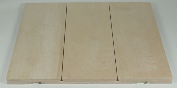
For larger series, you need a robustly constructed assembly board. We offer you the Prodboard as a basis. The external dimensions and cable slots are identical to the Devboard, so you can copy the installation plan directly from the Devboard.
If you wrap the cable harnesses by hand, it is more practical if you mount the measuring adapters and the guide elements on spacer columns high enough for the rolls of wrapping material to fit between the cable harness and the assembly board.
Depending on your requirements, you can unscrew the measuring adapters from the Panduit Quick-Build mounting plates and screw them to the Prodboard or you can build your own set of measuring adapters for production. In this case, the assembly with Kitconnect also saves you time compared to mounting mating connectors directly on the assembly board. You can have several employees assemble the set of measuring adapters at separate workstations at the same time without getting in each other's way.
You can also very quickly reconnect the cabling with the measurement technology as you had noted on the installation plan.
To be able to quickly reconnect the assembly board after a change, label the ribbon cables of the measurement technology on the side of the transfer modules.
| Devboard | Prodboard | |
| Execution | ||
| Covering | Panduit Quick-Build | birch plywood 18 mm |
| Width | 3 ft = 915 mm | 3 ft = 915 mm |
| Length | 3 ft = 915 mm 6 ft = 1830 mm |
3 ft = 915 mm 6 ft = 1830 mm |
| Locking on Kabelporter table | yes | yes |
| Distance between cross slots for measurement cables | 300 mm | 300 mm |
| Laying the measurement cables | from above | from above |
| Advantages | ||
| Time saving when setting up a new cable harness | ++ | + |
| Tool-free assembly | ++ | - |
| Quick changeability | ++ | + |
| Complete recycling of all parts | ++ | ++ |
| Distance to the board for easy bandaging | ++ | 0 |
| Absorption of forces during laying and pinning | - | ++ |
| Service life | 0 | ++ |
| Material costs | 0 | + |
| Suitability for | ||
| Small series | ++ | - |
| Pilot series | ++ | 0 |
| Years of series productions | 0 | ++ |
| Temporary set-up for production peaks | ++ | 0 |
| Spare parts production after end of series | ++ | 0 |
The grid sheet helps you to copy and archive assembly boards.
Ideally, you should place a grid sheet on the Devboard when you set up a new wiring harness for the first time. When setting up, mark the positions of all guide elements and mating connectors. When you dismantle the assembly board, you can scan the grid sheet and then archive it, print it out or use it as the basis for a CAD drawing.
Even if you set up the first installation board directly on a Prodboard, it is advantageous if you lay down a laminated grid sheet beforehand. This gives the assembly board a well-protected and easy-to-clean surface. To create a drawing, you can simply read off the position of the guide elements and mating connectors from the printed coordinates.
You can obtain ready-printed grid sheets from us or download them free of charge. You can either plot the downloaded grid sheets yourself or order printouts, possibly laminated, from a repro service, which will also scan grid sheets and print out edited copies for you.
Email: info@kabelassistent.eu
Tel.: ++49 / 76 35 / 82 716 50
Fax: ++49 / 76 35 / 82 716 20
It is generally possible to use our website without providing personal data.